Tag Archive for HA

What’s new in MySQL 5.6 Replication – free webinar

Global Transaction IDs - simplifying replication management

There will be a webinar this Wednesday where you can get the latest information on all of the great new content that has been included in the MySQL 5.6 Development Releases as well as some features that are still being developed. As always, the webinar is free but you need to register here in advance. Even if you can’t attend the live event it’s worth registering so that you get sent the replay.

Some of the topics we’ll be discussing are:

  • Enhanced data integrity: Global Transactions Identifiers, Crash-Safe Slaves and Replication Event Checksums;
  • High performance: Multi-Threaded Slaves, Binlog Group Commit and Optimized Row-Based Replication;
  • Improved flexibility: Time Delayed Replication, Multi-Source Replication, Binlog API and Informational Log Events
The event starts on Wednesday, December 14, 2011: 09:00 Pacific time; 17:00 UK; 18:00 CET.


MySQL HA Solutions – webinar replay

If you were unable to attend the live webinar (or you want to go back and listen to it again) then it’s now available to view on-line here.

Databases are the center of today’s web and enterprise applications, storing and protecting an organization’s most valuable assets and supporting business-critical applications. Just minutes of downtime can result in significant lost revenue and dissatisfied customers. Ensuring database highly availability is therefore a top priority for any organization. Tune into this webcast to learn more.

The session discusses:

  1. Causes, effect and impact of downtime
  2. Methodologies to map applications to HA solution
  3. Overview of MySQL HA solutions
  4. Operational best practices to ensure business continuity


MySQL with Windows Server 2008 R2 Failover Clustering

Windows Server 2008 R2 Failover Clustering

Oracle has announced support for running MySQL on Windows Server Failover Clustering (WSFC); with so many people developing and deploying MySQL on Windows, this offers a great option to add High Availability to MySQL deployments if you don’t want to go as far as deploying MySQL Cluster.

This post will give a brief overview of how to set things up but for all of the gory details a new white paper MySQL with Windows Server 2008 R2 Failover Clustering is available – please give me any feedback. I will also be presenting on this at a free webinar on Thursday 15th September (please register in advance) as well at an Oracle OpenWorld session in San Francisco on Tuesday 4th October (Tuesday, 01:15 PM, Marriott Marquis – Golden Gate C2) – a good opportunity to get more details and get your questions answered.

It sometimes surprises people just how much MySQL is used on Windows, here are a few of the reasons:

  • Lower TCO
    • 90% savings over Microsoft SQL Server
    • If your a little skeptical about this then try it out for yourself with the MySQL TCO Savings Calculator
  • Broad platform support
    • No lock-in
    • Windows, Linux, MacOS, Solaris
  • Ease of use and administration
    • < 5 mins to download, install & configure
    • MySQL Enterprise Monitor & MySQL WorkBench
  • Reliability
    • 24×7 Uptime
    • Field Proven
  • Performance and scalability
    • MySQL 5.5 delivered over 500% performance boost on Windows.
  • Integration into Windows environment
    • ADO.NET, ODBC & Microsoft Access Integration
    • And now, support for Windows Server Failover Clustering!
Probably the most common form of High Availability for MySQL is MySQL (asynchronous or semi-synchronous replication) and the option for the highest levels of availability is MySQL Cluster. We are in the process of rolling out a number of solutions that provide levels of availability somewhere in between MySQL Replication and MySQL Cluster; Oracle VM Template for MySQL Enterprise Edition was the first (overview, webinar replay, white paper) and WSFC is the second.


Solution Overview

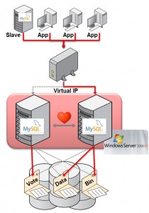
MySQL with Windows Failover Clustering requires at least 2 servers within the cluster together with some shared storage (for example FCAL SAN or iSCSI disks). For redundancy, 2 LANs should be used for the cluster to avoid a single point of failure and typically one would be reserved for the heartbeats between the cluster nodes.

The MySQL binaries and data files are stored in the shared storage and Windows Failover Clustering ensures that at most one of the cluster nodes will access those files at any point in time (hence avoiding file corruptions).

Clients connect to the MySQL service through a Virtual IP Address (VIP) and so in the event of failover they experience a brief loss of connection but otherwise do not need to be aware that the failover has happened other than to handle the failure of any in-flight transactions.

Target Configuration

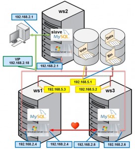
This post will briefly step through how to set up and use a cluster and this diagrams shows how this is mapped onto physical hardware and network addresses for the lab used later in this post. In this case, iSCSI is used for the shared storage. Note that ideally there would be an extra subnet for the heartbeat connection between ws1 and ws3.

This is only intended to be an overview and the steps have been simplified refer to the white paper for more details on the steps.

Prerequisites

  • MySQL 5.5 & InnoDB must be used for the database (note that MyISAM is not crash-safe and so failover may result in a corrupt database)
  • Windows Server 2008 R2
  • Redundant network connections between nodes and storage
  • WSFC cluster validation must pass
  • iSCSI or FCAL SAN should be used for the shared storage

Step 1 Configure iSCSI in software (optional)

Create 2 clustered disks

This post does not attempt to describe how to configure a highly available, secure and performant SAN but in order to implement the subsequent steps shared storage is required and so in this step we look at one way of using software to provide iSCSI targets without any iSCSI/SAN hardware (just using the server’s internal disk). This is a reasonable option to experiment with but probably not what you’d want to deploy with for a HA application. If you already have shared storage set up then you can skip this step and use that instead.

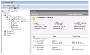
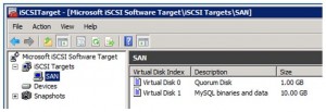
As part of this process you’ll create at least two virtual disks within the iSCSI target; one for the quorum file and one for the MySQL binaries and data files. The quorum file is used by Windows Failover Clustering to avoid “split-brain” behaviour.

Step 2. Ensure Windows Failover Clustering is enabled

Ensure that WSFC is enabled

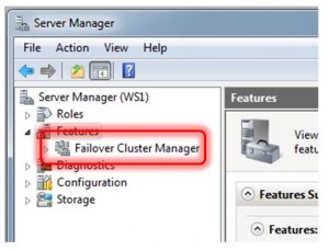
To confirm that Windows Failover Clustering is installed on ws1 and ws3, open the “Features” branch in the Server Manager tool and check if “Failover Cluster Manager” is present.

If Failover Clustering is not installed then it is very simple to add it. Select “Features” within the Service Manager and then click on “Add Features” and then select “Failover Clustering” and then “Next”.


Step 3. Install MySQL as a service on both servers

Install MySQL as a Windows Service

If MySQL is already installed as a service on both ws1 and ws3 then this step can be skipped.

The installation is very straight-forward using the MySQL Windows Installer and selecting the default options is fine.

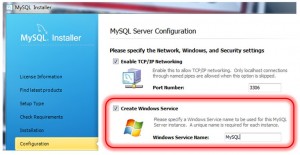
Within the MySQL installation wizard, sticking with the defaults is fine for this exercise. When you reach the configuration step, check “Create Windows Service”.

The installation and configuration must be performed on both ws1 and ws2, if necessary.

Step 4. Migrate MySQL binaries & data to shared storage

If the MySQL Service is running on either ws1 or ws3 then stop it – open the Task Manager using ctrl-shift-escape, select the “Services” tab and then right-click on the MySQL service and choose “Stop Service”.

As the iSCSI disks were enabled on ws1 you can safely access them in order to copy across the MySQL binaries and data files to the shared disk.

Step 5. Create Windows Failover Cluster

Create the Cluster (without MySQL)

From the Server Manager on either ws1 or ws3 navigate to “Features -> Failover Cluster Manager” and then select “Validate a Configuration”. When prompted enter ws1 as one name and then ws3 as the other.

In the “Testing Options” select “Run all tests” and continue. If the tests report any errors then these should be fixed before continuing.

Now that the system has been verified, select “Create a Cluster” and provide the same server names as used in the validation step. In this example, “MySQL” is provided as the “Cluster Name” and then the wizard goes on to create the cluster.

Step 6. Create Cluster of MySQL Servers within Windows Cluster

Cluster the MySQL Service

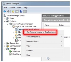
Adding the MySQL service to the new Cluster is very straight-forward. Right-click on “Services and applications” in the Server Manager tree and select “Configure a Service or Application…”. When requested by the subsequent wizard, select “Generic Service” from the list and then “MySQL” from the offered list of services. Our example name was “ClusteredMySQL”. Please choose an appropriate name for your cluster. The wizard will then offer the shared disk that has not already been established as the quorum disk for use with the Clustered service – make sure that it is selected.

Once the wizard finishes, it starts up the MySQL Service. Click on the “ClusteredMySQL” service branch to observe that the service is up and running. You should also make a note of the Virtual IP (VIP) assigned, in this case 192.168.2.18.

Step 7. Test the cluster

As described in Step 6, the VIP should be used to connect to the clustered MySQL service:

C: mysql –u root –h 192.168.2.18 –P3306 –pbob

From there create a database and populate some data.

mysql> CREATE DATABASE clusterdb;
mysql> USE clusterdb;
mysql> CREATE TABLE simples (id int not null primary key) ENGINE=innodb;
mysql> REPLACE INTO simples VALUES (1);
mysql> SELECT * FROM simples;
+----+
| id |
+----+
| 1 |
+----+

Migrate MySQL Service Across Cluster

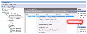
The MySQL service was initially created on ws1 but it can be forced to migrate to ws3 by right-clicking on the service and selecting “Move this service or application to another node”.

As the MySQL data is held in the shared storage (which has also been migrated to ws3), it is still available and can still be accessed through the existing mysql client which is connected to the VIP:

mysql> select * from simples; 
ERROR 2006 (HY000): MySQL server has gone away 
No connection. Trying to reconnect... 
Connection id: 1 
Current database: clusterdb 
+----+ 
| id | 
+----+ 
| 1 | 
+----+

Note the error shown above – the mysql client loses the connection to the MySQL service as part of the migration and so it automatically reconnects and complete the query. Any application using MySQL with Windows Failover Cluster should also expect to have to cope with these “glitches” in the connection.

Conclusion

More users develop and deploy and MySQL on Windows than any other single platform. Enhancements in MySQL 5.5 increased performance by over 5x compared to previous MySQL releases. With certification for Windows Server Failover Clustering, MySQL can now be deployed to support business critical workloads demanding high availability, enabling organizations to better meet demanding service levels while also reducing TCO and eliminating single vendor lock-in.
Please let me know how you get on by leaving comments on this post.


London 18th October: Oracle Technology Network MySQL Developer Day

I will be presenting on MySQL Cluster and MySQL Replication at the Oracle Technical Network MySQL Developer day in London on Tuesday, 18 October 2011 (8:30 AM – 4:00 PM). It’s free but you need to register here while there are still places (attendance has been extremely high at other locations).

The MySQL Developer Day is a one-stop shop for you to learn all the essential MySQL skills. In this free, one-day seminar, we will cover everything you need to know to successfully design, develop, and manage your MySQL databases. You’ll also learn the guidelines and best practices in performance tuning and scalability.

Attend this event and gain the knowledge to:

  • Develop your new applications cost-effectively using MySQL
  • Improve performance of your existing MySQL databases
  • Manage your MySQL environment more efficiently

Agenda:

8:30 a.m. – 9:30 a.m. Registration
9:30 a.m. – 10:30 a.m. Keynote: MySQL Essentials
10:30 a.m. – 11:30 p.m. Session: MySQL Replication and Scalabilit
11:30 a.m. – 11:45 a.m. Break
11:45 a.m. – 12:45 p.m. Session: MySQL Cluster
12:45 p.m. – 1:30 p.m. Lunch
1:30 p.m. – 2:30 p.m. Session: MySQL Administration and Management Tools
2:30 p.m. – 3:30 p.m. Session: MySQL Performance Tuning
3:30 p.m. – 4:00 p.m. Close

If you’re going to be in the area, please register and come along – would be good to meet as many of you as possible.


My sessions at Oracle OpenWorld 2011

Slight adjustment to some of the times + added the MySQL community reception (read  vodka!). Oracle OpenWorld (San Francisco) starts on Sunday 2nd October (including some MySQL community sessions) through Thursday 6th October. MySQL has a lot of sessions this year as well as 3 demo booths.

This year I’m going to be involved in 3 public sessions – if you’re attending, please come along and say hello!

  • Getting the Most Out of MySQL on Windows – 13:15 on Tuesday (Marriott Marquis – Golden Gate C2)
  • Building Highly Available and Scalable Real-Time Services with MySQL Cluster – 10:15 on Wednesday (Marriott Marquis – Golden Gate C1)
  • NoSQL Access to MySQL: The Best of Both Worlds – 11:45 on Wednesday (Marriott Marquis – Golden Gate C1)
  • MySQL Community Reception – 19:00 on Wednesday (San Francisco Marriott Marquis – Foothill G)
In addition I’ll be spending as much time as I can at the MySQL demo booths in the exhibition hall. Come and visit us for demos of MySQL Cluster, MySQL Enterprise Edition and MySQL WorkBench.


White Paper – Oracle VM Template for MySQL Enterprise Edition

HA Provided by OVM

A new white paper is available that steps you though the benefits and the use of the Oracle VM Template for MySQL Enterprise Edition (also see yesterday’s press announcement). Get the white paper here.

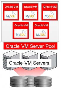
As a reminder Oracle Virtual Manager provides a way to add High Availability to your MySQL deployment (this is separate from MySQL Replication and MySQL Cluster). The new OVM template provides a very convenient way to create one or more Virtual Machines that come pre-provisioned with OVM, Oracle Linux and MySQL Enterprise Edition as well as the scripts required to integrate MySQL into OVM’s HA features.


New – Oracle VM Template for MySQL Enterprise Edition

Oracle VM Template for MySQL Enterprise Edition

Oracle today announced the release of the “Oracle VM Template for MySQL Enterprise Edition” – you can read the press-release here.

There are a couple of ways to look at the benefits:

  • Provides a simple alternate High Availability solution for MySQL (i.e. rather than MySQL Replication or MySQL Cluster – although you can still set up replication to/from a MySQL Server installed this way)
  • A new, very simple way to get up and running with MySQL Enterprise – running on a complete stack that Oracle can provide support for

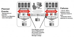
As the focus of this blog is normally MySQL Cluster and Replication, the HA attributes of this solution are probably those of most interest. When you download the template and then load it into Oracle Virtual Machine (OVM) Manager and fire it up you get the chance to flag that you want it to be run in a HA mode. What this means is that:

  • If the hardware, virtual machine, operating system or MySQL Server fail then the OVM Manager will recreate the VM on another physical server from the OVM Server Pool
  • For routine hardware maintenance you can tell OVM Manager to migrate a running VM to another physical server

Note that the data files are actually stored on shared storage under Oracle Cluster File System 2 (OCFS2) which is how a newly instantiated replacement VM can get up and running quickly. As the original hardware (or the MySQL Server instance, OS or VM) could still fail without warning the MySQL Storage Engine must be crash-safe and so this should be used with InnoDB rather than MyISAM.

The complete software line-up looks like this:

  • Oracle Linux 5 Update 6 with the Unbreakable Enterprise Kernel
  • Oracle VM 2.2.1
  • Oracle VM Manager 2.1.5
  • Oracle Cluster File System 2 (OCFS2)
  • MySQL Database 5.5.10 (Enterprise Edition) – InnoDB


MySQL Cluster: Geographic Replication Deep-Dive webinar

I will be presenting a free Webinar on Geographic Replication for MySQL Cluster at 9:00 am (UK time) on Tuesday 24 November.
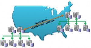
Multi-Master Replication for HA with MySQL Cluster

Multi-Master Replication for HA with MySQL Cluster

MySQL Cluster has been deployed into some of the most demanding web, telecoms and enterprise /
government workloads, supporting 99.999% availability with real time performance and linear write scalability.

You can register on-line here.

Tune into this webinar where you can hear from the MySQL Cluster product management team provide a detailed “deep dive” into one of MySQL Cluster’s key capabilities – Geographic Replication.

In this session, you will learn how using Geographic Replication enables your applications to:

  • Achieve higher levels of availability within a data center or across a WAN
  • Locate data closer to users, providing lower latency access
  • Replicate to other MySQL storage engines for complex data analysis and reporting of real time data
  • Gow to get started with Geographic Replication

Tuesday, November 24, 2009: 10:00 Central European time

  • Tue, Nov 24:  09:00 Western European time
  • Tue, Nov 24:  11:00 Eastern European time

The presentation will be approximately 1 hour long, including on-line Q&A.


MySQL Cluster fault tolerance – impact of deployment decisions

Typical management configuration

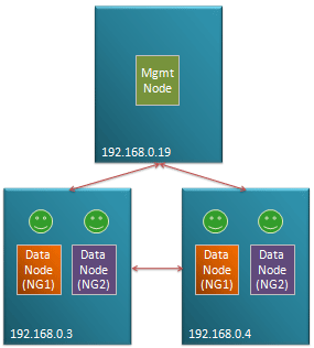
Fig 1. Typical management configuration

MySQL Cluster is designed to be a High Availability, Fault Tolerant database where no single failure results in any loss of service.

This is however dependent on how the user chooses to architect the configuration – in terms of which nodes are placed on which physical hosts, and which physical resources each physical host is dependent on (for example if the two blades containing the data nodes making up a particular node group are cooled by the same fan then the failure of that fan could result in the loss of the whole database).

Of course, there’s always the possibility of an entire data center being lost due to earthquake, sabotage etc. and so for a fully available system, you should consider using asynchronous replication to a geographically remote Cluster.

Fig 1. illustrates a typical small configuration with one or more data nodes from different node groups being stored on two different physical hosts and a management node on an independent machines (probably co-located with other applications as its resource requirements are minimal. If any single node (process) or physical host is lost then service can continue.

The basics of MySQL Cluster fault tolerance

Data held within MySQL Cluster is partitioned, with each node group being responsible for 2 or more fragments. All of the data nodes responsible for the same fragments form a Node Group (NG). If configured correctly, any single data node can be lost and the other data nodes within its node group will continue to provide service.

The management node (ndb_mgmd process) is required when adding nodes to the cluster – either when it was initially configured or when a node has been lost and restarted.

A heart-beat protocol is used between the data nodes in order to identify when a node has been lost. In many cases, the community of surviving data nodes can reconfigure themselves but in some cases they need help from the management node – much of this article focuses on how to identify these cases so that you can decide what level of redundancy is required for the management node.

Goals of the algorithm

The algorithm used by MySQL Cluster has 2 priorities (in order):

  1. Prevent database inconsistencies through “split brain” syndrome
  2. Keep the database up and running, serving the application

Split brain would occur if 2 data nodes within a node group lost contact with each other and independently decided that they should be master for the fragments controlled by their node group. This could lead to them independently applying conflicting changes to the data – making it very hard to recover the database (which would include undoing the changes that the application believes to have been safely committed). Note that a particular node doesn’t know whether its peer(s) has crashed or if it has just lost its connection to it. If the algorithm is not confident of avoiding a split brain situation then all of the data nodes are shut down – obviously that isn’t an ideal result and so it’s important to understand how to configure your cluster so that doesn’t happen.

The algorithm

If all of the data nodes making up a node group are lost then the cluster shuts down.

When data nodes lose contact with each other (could be failure of a network connection, process or host) then all of the data nodes that can still contact each other form a new community. Each community must decide whether its data nodes should stay up or shut down:

  • If the community doesn’t contain at least 1 data node from each node group then it is not viable and its data nodes should shut down.
  • If this community is viable and it can determine that it contains enough of the data nodes such that there can be no other viable community out there (one with at least 1 data node from each node group) then it will decide (by itself) to keep up all of its data nodes.
  • If the community is viable but there is the possibility of another viable community then it contacts the arbitrator which decides which amongst all viable communities should be allowed to stay up. If the community can not connect to the arbitrator then its data nodes shut down.

In this way, at most one community of data nodes will survive and there is no chance of split brain.

The arbitrator will typically run on a management node. As you’ll from the algorithm and the following examples, the cluster can sometimes survive a failure without needing a running management node but sometimes it can’t. In most of the examples, a single management node is used but you may well decide to have a second for redundacy so that more multiple-point-of-failures can be handled. At any point in time, just one of the management nodes would act as the active arbitrator, if the active one is lost then a majority community of data nodes can hand control over to the other management node.

Note that the management node consumes very little resource and so can be co-located with other functions/applications but as you’ll see from the examples, you would normally avoid running it on the same host as a data node.

Example 1: Simplest cluster – loss of management node followed by a data node
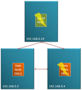
Fig 2. Loss of management node followed by data node in a simple Cluster

Fig 2. Loss of management node followed by data node in a simple Cluster

Fig 2. shows a very simple cluster with 3 hosts, the management node running on 192.168.0.19 and then a single node group (NG1) made up of 2 data nodes split between 192.168.0.3 and 192.168.0.4. In this scenario, the management node is ‘lost’ (could be process, host or network failure) followed by one of the data nodes.

The surviving data node forms a community of 1. As it can’t know whether the other data node from NG1 is still viable and it can’t contact the arbitrator (the management node) it must shut itself down and so service is lost.

Note that the 2 nodes could be lost instantaneously or the management node might be lost first followed some time later by a data node.

To provide a truly HA solution there are 2 steps:

  1. Ensure that there is no single point of failure that could result in 192.168.0.19 and either of the other 2 hosts being lost.
  2. Run a second management node on a 4th host that can take over as arbitrator if 192.168.0.19 is lost

Example 2: Half of data nodes isolated but management node available
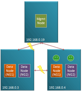
Fig 3. Half of data nodes lost

Fig 3. Half of data nodes lost

In Fig 3. host 192.168.0.3 and its 2 data nodes remains up and running but becomes isolated from the management node and the other data nodes. 2 communities of connected data nodes are formed. As each of these communities are viable but recognize that there could be another viable surviving communitycontain a data node from each node group, they must defer to the management node. As192.168.0.3 has lost it’s connection to the management node, the community of data nodes hosted there shut themselves down. The community hosted on 192.168.0.4 can contact the management node which as it’s the only community it can see, allows its data nodes to stay up and so service is maintained.

.

.

.

Example 3: Half of data nodes isolated and management node lost
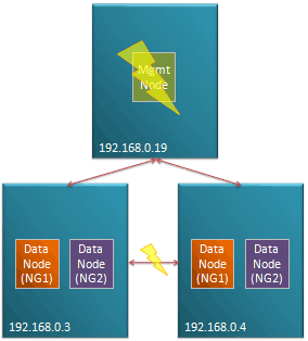
Fig 4. Data nodes isolated following loss of management node

Fig 4. Data nodes isolated following loss of management node

The scenario shown in Fig 4. builds upon Example 2 but in the case, the management node is lost before one of the data node hosts loses its connection to the other.

In this case, both communities defer to the management node but as that has been lost they both shut themselves down and service is lost.

Refer to Example 1 to see what steps could be taken to increase the tolerance to multiple failures.

.

.

.

.

.

Example 4: Management node co-located with data nodes
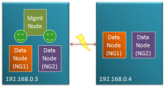
Fig 4. Management node co-located with data nodes

Fig 5. Management node co-located with data nodes

Fig. 4 shows a common, apparent short-cut that people may take, with just 2 hosts available hosting the management node of the same machine as some of the data nodes. In this example, the connection between the 2 hosts is lost. As each community is viable they each attempt to contact the arbitrator – the data nodes on 192.168.0.3 are allowed to stay up while those on 192.168.0.4 shut down as they can’t contact the management node.

However this configuration is inherently unsafe, if 192.168.0.3 failed then there would be a complete loss of service as the data nodes on 192.168.0.4 would form a viable community but be unable to confirm that they represent the only viable community.

It would be tempting to make this more robust by running a second management node on 192.168.0.4 – in that case, when each host becomes isolated from the other, the data nodes local to the management node that’s the current arbitrator will stay up however if the entire host on which the active arbitrator failed then you would again lose service. The management node must be run on a 3rd host for a fault-tolerant solution.

Example 5: Odd number of data node hosts
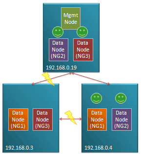
Fig 6. Isolation of data node host - majority survive

Fig 6. Isolation of data node host - majority survive

Fig 6. shows a configuration running the management node on the same host as some of the data nodes does provide a robust solution.

In this example 192.168.0.3 becomes isolated its data nodes form a community of 2 which doesn’t include a data node from NG2 and so they shut themselves down. 192.168.0.4 and 192.168.0.19 are still connected and so they form a commiunity of 4 data nodes; they recognize that the community holds all data nodes from NG2 and so there can be no other viable community and so they are kept up without having to defer to the arbitrator.

Note that as there was no need to consult the management node, service would be maintained even if it was the machine hosting the management node that became isolated.

.

.

Example 6: Loss of all data nodes in a node group
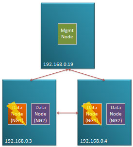
Fig 7. All data nodes in a node-group lost

Fig 7. All data nodes in a node-group lost

Fig 7. illustrates the case where there are multiple data node failures such that all of the data nodes making up a node group are lost. In this scenario, the cluster has to shut down as that node group is no longer viable and the cluster would no longer be able to provide access to all data.

.

.

.

.

.

.

Example 7: Loss of multiple data nodes from different node groups
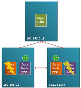
Fig 8. Data nodes from different node-groups lost

Fig 8. Data nodes from different node-groups lost

Fig 8. is similar to Example 6 but in this case, there is still a surviving data node from each node group. The surviving data node from NG1 forms a community with the one from NG2. As there could be another viable community (containing a data node from NG1 and NG2), they defer to the management node and as they form the only viable community they’re allowed to stay up.

.

.

.

.

.

.

Example 8: Classic, fully robust configuration
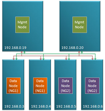
Fig 8. Robust configuration

Fig 9. Robust configuration

Fig 9. shows the classic, robust configuration. 2 independent machines both host management nodes. These are in turn connected by 2 independent networks to each of the data nodes (which are in turn all connected to each other via duplicated network connections).


MySQL Cluster – flexibility of replication

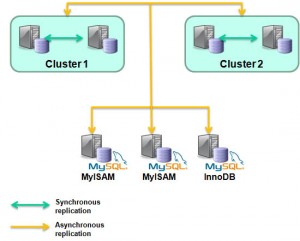
One of the better kept secrets about MySQL Cluster appears to be the flexibility available when setting up replication. Rather than being constrained to implementing a single replication scheme, you can mix and match approaches.

Just about every Cluster deployment will use synchronous replication between the data nodes within a node group to implement High Availability (HA) by making sure that at the point a transaction is committed, the new data is stored in at least 2 physical hosts. Given that MySQL Cluster is usually used to store the data in main memory rather than on disk, this is pretty much mandatory (note that the data changes are still written to disk but that’s done asynchronously to avoid slowing down the database).

MySQL Cluster Replication

MySQL Cluster Replication

MySQL asynchronous replication is often used for MySQL Cluster deployments in order to provide Geographic Redundancy. At the same time as the synchronous replication within a Cluster, the changes can be replicated asynchronously to a second Cluster (or to more than one) at a remote location. Asynchronous rather than synchronous replication is used so that the transaction commit is not delayed while waiting for the remote (could be thousands of miles away, connected by a high latency WAN) Cluster to receive, apply and acknowledge the change. A common misconception is that changes being made through the NDB API will not be replicated to the remote site as this replication is handled by a MySQL Server instance – the reality is that the MySQL Replication implementation will pick up the changes even when they’re written directly to the data nodes through the NDB API.

A third use of replication is to store the Cluster’s data in a seperate database – for example to have a read-only, up-to-date copy of the data stored within the MyISAM storage engine so that complex reports can be generated from it. And the best news is that this can be done at the same time as the local HA and remote Geographic Redundancy replication!

Johan’s Blog provides the technical details around configuring replication in order to provide some extra scaling by setting up non-Cluster slave databases that pick up all changes from the Cluster database.