Tag Archive for MySQL Cluster CGE

MySQL Cluster 6.3.31b source released

The source version for MySQL Cluster 6.3.31b has now been made available at ftp://ftp.mysql.com/pub/mysql/download/cluster_telco/mysql-5.1.41-ndb-6.3.31b/

This replaces MySQL Cluster 6.3.30 and 6.3.31.

You can either wait for the binaries to be released or if you’re in a rush then you can find instructions on building the binaries for yourself in the earlier article: “MySQL Cluster 7.0.7 source released“.

A description of all of the changes (fixes) that have gone into MySQL Cluster 6.3.31b (compared to 6.3.30) can be found in the MySQL Cluster 6.3.31b Change Log


MySQL Cluster 7.0.11b source released

The source version for MySQL Cluster 7.0.11b has now been made available at ftp://ftp.mysql.com/pub/mysql/download/cluster_telco/mysql-5.1.41-ndb-7.0.11b/

This replaces MySQL Cluster 7.0.10 and 7.0.11.

You can either wait for the binaries to be released or if you’re in a rush then you can find instructions on building the binaries for yourself in the earlier article: “MySQL Cluster 7.0.7 source released“.

A description of all of the changes (fixes) that have gone into MySQL Cluster 7.0.11b (compared to 7.0.10) can be found in the MySQL Cluster 7.0.11b Change Log


MySQL Cluster Performance Tuning Best Practices – Webinar replay available

For anyone that missed the recent webinar on getting the best performance out of MySQL Cluster then the replay is now available from mysql.com.

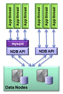
Benefits of connection pooling

Benefits of connection pooling

Are you experiencing current performance bottlenecks in your high availability applications ? Are you designing a new mission-critical application and want to know how best to structure your schema and index strategy for optimal performance? Interested in how to transform your SQL into faster, more efficient queries?

Then this free web presentation is for you! You will get expert insight and learn best practices to help you identify those areas of database and application design that will give you the greatest benefits for performance when using MySQL Cluster.

It discusses guidelines and best practices covering the following areas:

  • General Design Concepts and Guidelines
  • Schema Optimization
    • BLOB/Text vs VARBINARY/VARCHAR
    • Partition by Key
  • Index Selection and Tuning
  • Basic Query Tuning
  • MySQL Cluster Parameter Tuning Guidelines
  • Tools to accelerate application development and testing


Using NDBINFO – example of monitoring data nodes with MySQL Enterprise Monitor

You may have read Bernd’s recent post that explained how to try out some new beta functionality for MySQL Cluster and wondered what kind of use you could put the new ndb$info to. ndb$info uses tables/views to give real-time access to a whole host of information that helps you monitor and tune your MySQL Cluster deployment. This article gives one example, extending MySQL Enterprise Monitor to keep an eye on the amount of free memory on the data nodes and then raise an alarm when it starts to run low – even generating SNMP traps if that’s what you need.

One of the features of MySQL Enterprise Monitor is that you can define custom data collectors and that those data collectors can run SQL queries to get the data. The information retrieved by those custom data collectors can then be used with rules that the user defines through the MySQL Enterprise Monitor GUI to create warning/alarms.

In this example, I create two new data collectors and store the files in the “<MySQL Enterprise Monitor installation directory>/agent/share/mysql-proxy/items/” directory before starting up the MySQL Enterprise Monitor agents:

cluster_max_used.xml:

<?xml version="1.0" encoding="utf-8"?>
<classes>
  <class>
    <namespace>mysql</namespace>
    <classname>cluster_max_used</classname>
    <query><![CDATA[SELECT MAX(used) as Used FROM ndbinfo.memoryusage
      WHERE DATA_MEMORY = 'DATA_MEMORY']]>
    </query>
  </class>
</classes>

cluster_min_avail.xml:

<?xml version="1.0" encoding="utf-8"?>
<classes>
  <class>
    <namespace>mysql</namespace>
    <classname>cluster_min_avail</classname>
    <query><![CDATA[SELECT MIN(max)as Max FROM ndbinfo.memoryusage
       WHERE DATA_MEMORY = 'DATA_MEMORY']]>
    </query>
  </class>
</classes>

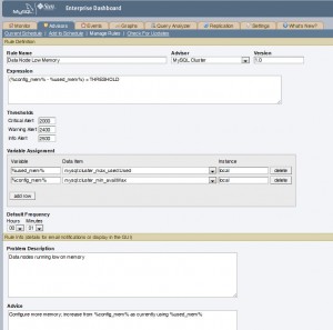
Fig. 1 Rule definition

In MySQL Enterprise Monitor, rules are grouped together into Advisors and so I create a new Advisor called “MySQL Cluster” and then create just one new rule within that Advisor group.

As shown in Fig. 1 the rule is called “Data Node Low Memory”. The “Variable Assignment” section is used to define 2 variables %used_mem% and %config_mem% which are populated from the Used and Max results from the 2 new data collectors. The “Expression” section is used to test “(Max Used) < THRESHOLD” and then the values to be substituted for THRESHOLD are defined in the “Thresholds” section – indicating at what points the Info, Warning and Critical Alters should be raised.

There are then a number of optional sections that you can use to add useful information to the person investigating the alert.

Once the rule has been created, the next step is to schedule it and (if desired) tag that the alerts should also result in SNMP traps being raised. This is standard MySQL Enterprise Monitor practice and so it isn’t explained here except to point out that this rule is monitoring information from the data nodes but the rule has to be applied to a MySQL Server (MySQL Enterprise Monitor has no idea what a data node is) and so you need to schedule the rule against one or more arbitrary MySQL Server instances in the Cluster.

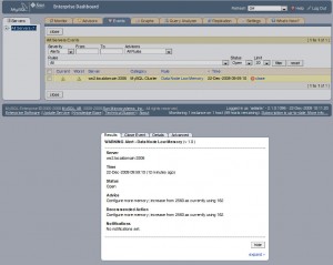
Fig. 2 Warning alert


To test the functionality, start adding more data to your MySQL Cluster until the Warning alert is triggered as shown in Fig. 2. As you can see, the optional information we included is shown – including values from Used and Max.


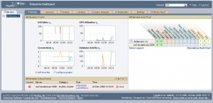
Fig. 3 Critical alarm

I then add more data to the database until the critical alert is raised and confirm that it’s displayed on the main monitoring panel of the MySQL Enterprise Monitor dashboard. Note that if you requested these alerts be included with the SNMP feed then SNMP traps will also be raised.

Please note that this example is intended to illustrate the mechanics of setting up monitoring on an arbitrary piece of data from ndbinfo and obviously in the real world you would want to monitor more than just the memory and even for the memory, you might want to use a more sophisticated rule.


MySQL Cluster 7.0.11 source released

The source version for MySQL Cluster 7.0.11 has now been made available at ftp://ftp.mysql.com/pub/mysql/download/cluster_telco/mysql-5.1.41-ndb-7.0.11/

This replaces MySQL Cluster 7.0.10.

You can either wait for the binaries to be released or if you’re in a rush then you can find instructions on building the binaries for yourself in the earlier article: “MySQL Cluster 7.0.7 source released“.

A description of all of the changes (fixes) that have gone into MySQL Cluster 7.0.11 (compared to 7.0.11) can be found in the MySQL_Cluster_7_0_11_ChangeLog.


Upcoming webinars for Java and JPA access to MySQL Cluster

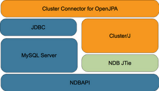
ClusterJ Architecture

ClusterJ Architecture

MySQL have been working on a new way of accessing MySQL Cluster using Java. Designed for Java developers, the MySQL Cluster Connector for Java implements an easy-to-use and high performance native Java interface and OpenJPA plug-in that maps Java classes to tables stored in the high availability, real-time MySQL Cluster database.

There is a series of 2 webinars coming up, as always these are free to attend – you just need to register in advance:

Part 1: Tuesday, February 16, 2010: 10:00 Pacific time

  • an overview of the MySQL Cluster Connector for Java
  • what these technologies bring to Java developers
  • implementation details of the MySQL Cluster Java API and Plug-In for OpenJPA
  • configuring the connection to MySQL Cluster
  • creating the Java Domain Object Model for your tables
  • managing insert, update, and delete operations
  • querying the database
  • how to get started developing new Java applications using these interfaces

Tue, Feb 16: 08:00 Hawaii time
Tue, Feb 16: 11:00 Mountain time (America)
Tue, Feb 16: 12:00 Central time (America)
Tue, Feb 16: 13:00 Eastern time (America)
Tue, Feb 16: 18:00 UTC
Tue, Feb 16: 18:00 Western European time
Tue, Feb 16: 19:00 Central European time
Tue, Feb 16: 20:00 Eastern European time

Register for Part 1 here.

an overview of the MySQL Cluster Connector for Java
what these technologies bring to Java developers
implementation details of the MySQL Cluster Java API and Plug-In for OpenJPA
configuring the connection to MySQL Cluster
creating the Java Domain Object Model for your tables
managing insert, update, and delete operations
querying the database
how to get started developing new Java applications using these interfaces

Part 2: Wednesday, March 03, 2010: 10:00 Pacific time

  • how MySQL Cluster Connector for Java coexists with existing OpenJPA / TopLink / JDBC-based apps
  • how to evaluate the MySQL Cluster Connector for Java alternatives
  • performance comparisons with both existing Java access and with native NDB API access to MySQL Cluster
  • what the future holds for this technology

Wed, Mar 03: 08:00 Hawaii time
Wed, Mar 03: 11:00 Mountain time (America)
Wed, Mar 03: 12:00 Central time (America)
Wed, Mar 03: 13:00 Eastern time (America)
Wed, Mar 03: 18:00 UTC
Wed, Mar 03: 18:00 Western European time
Wed, Mar 03: 19:00 Central European time
Wed, Mar 03: 20:00 Eastern European time

Register for Part 2 here.

This functionality isn’t yet GA but it is available for you to try and we’d love to get feedback (which you can provide through the MySQL Cluster forum or by emailing cluster@lists.mysql.com

If you want to see for yourself then take a look at the Blog entry from Bernhard Ocklin – the engineering manager responsible for this work.


MySQL Cluster 7.0.10 source released

The source version for MySQL Cluster 7.0.10 has now been made available at ftp://ftp://ftp.mysql.com/pub/mysql/download/cluster_telco/mysql-5.1.39-ndb-7.0.10//

This replaces MySQL Cluster 7.0.9.

You can either wait for the binaries to be released or if you’re in a rush then you can find instructions on building the binaries for yourself in the earlier article: “MySQL Cluster 7.0.7 source released“.

A description of all of the changes (fixes) that have gone into MySQL Cluster 7.0.10 (compared to 7.0.9) can be found in the MySQL_Cluster_7_0_10_ChangeLog.


New white paper: Guide to Optimizing Performance of the MySQL Cluster Database

MySQL Cluster Connection Pooling

MySQL Cluster Connection Pooling

This guide explores how to tune and optimize the MySQL Cluster database to handle diverse workload requirements. It discusses data access patterns and how to build distribution awareness into applications, before exploring schema and query optimization, tuning of parameters and how to get the best out of the latest innovations in hardware design.

The Guide concludes with recent performance benchmarks conducted with the MySQL Cluster database, an overview of how MySQL Cluster can be integrated with other MySQL storage engines, before summarizing additional resources that will enable you to optimize MySQL Cluster performance with your applications.

Download the white paper (as always, for free) from: http://www.mysql.com/why-mysql/white-papers/mysql_wp_cluster_perfomance.php


MySQL Cluster fault tolerance – impact of deployment decisions

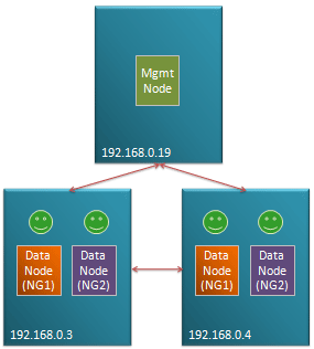
Typical management configuration

Fig 1. Typical management configuration

MySQL Cluster is designed to be a High Availability, Fault Tolerant database where no single failure results in any loss of service.

This is however dependent on how the user chooses to architect the configuration – in terms of which nodes are placed on which physical hosts, and which physical resources each physical host is dependent on (for example if the two blades containing the data nodes making up a particular node group are cooled by the same fan then the failure of that fan could result in the loss of the whole database).

Of course, there’s always the possibility of an entire data center being lost due to earthquake, sabotage etc. and so for a fully available system, you should consider using asynchronous replication to a geographically remote Cluster.

Fig 1. illustrates a typical small configuration with one or more data nodes from different node groups being stored on two different physical hosts and a management node on an independent machines (probably co-located with other applications as its resource requirements are minimal. If any single node (process) or physical host is lost then service can continue.

The basics of MySQL Cluster fault tolerance

Data held within MySQL Cluster is partitioned, with each node group being responsible for 2 or more fragments. All of the data nodes responsible for the same fragments form a Node Group (NG). If configured correctly, any single data node can be lost and the other data nodes within its node group will continue to provide service.

The management node (ndb_mgmd process) is required when adding nodes to the cluster – either when it was initially configured or when a node has been lost and restarted.

A heart-beat protocol is used between the data nodes in order to identify when a node has been lost. In many cases, the community of surviving data nodes can reconfigure themselves but in some cases they need help from the management node – much of this article focuses on how to identify these cases so that you can decide what level of redundancy is required for the management node.

Goals of the algorithm

The algorithm used by MySQL Cluster has 2 priorities (in order):

  1. Prevent database inconsistencies through “split brain” syndrome
  2. Keep the database up and running, serving the application

Split brain would occur if 2 data nodes within a node group lost contact with each other and independently decided that they should be master for the fragments controlled by their node group. This could lead to them independently applying conflicting changes to the data – making it very hard to recover the database (which would include undoing the changes that the application believes to have been safely committed). Note that a particular node doesn’t know whether its peer(s) has crashed or if it has just lost its connection to it. If the algorithm is not confident of avoiding a split brain situation then all of the data nodes are shut down – obviously that isn’t an ideal result and so it’s important to understand how to configure your cluster so that doesn’t happen.

The algorithm

If all of the data nodes making up a node group are lost then the cluster shuts down.

When data nodes lose contact with each other (could be failure of a network connection, process or host) then all of the data nodes that can still contact each other form a new community. Each community must decide whether its data nodes should stay up or shut down:

  • If the community doesn’t contain at least 1 data node from each node group then it is not viable and its data nodes should shut down.
  • If this community is viable and it can determine that it contains enough of the data nodes such that there can be no other viable community out there (one with at least 1 data node from each node group) then it will decide (by itself) to keep up all of its data nodes.
  • If the community is viable but there is the possibility of another viable community then it contacts the arbitrator which decides which amongst all viable communities should be allowed to stay up. If the community can not connect to the arbitrator then its data nodes shut down.

In this way, at most one community of data nodes will survive and there is no chance of split brain.

The arbitrator will typically run on a management node. As you’ll from the algorithm and the following examples, the cluster can sometimes survive a failure without needing a running management node but sometimes it can’t. In most of the examples, a single management node is used but you may well decide to have a second for redundacy so that more multiple-point-of-failures can be handled. At any point in time, just one of the management nodes would act as the active arbitrator, if the active one is lost then a majority community of data nodes can hand control over to the other management node.

Note that the management node consumes very little resource and so can be co-located with other functions/applications but as you’ll see from the examples, you would normally avoid running it on the same host as a data node.

Example 1: Simplest cluster – loss of management node followed by a data node
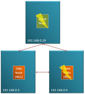
Fig 2. Loss of management node followed by data node in a simple Cluster

Fig 2. Loss of management node followed by data node in a simple Cluster

Fig 2. shows a very simple cluster with 3 hosts, the management node running on 192.168.0.19 and then a single node group (NG1) made up of 2 data nodes split between 192.168.0.3 and 192.168.0.4. In this scenario, the management node is ‘lost’ (could be process, host or network failure) followed by one of the data nodes.

The surviving data node forms a community of 1. As it can’t know whether the other data node from NG1 is still viable and it can’t contact the arbitrator (the management node) it must shut itself down and so service is lost.

Note that the 2 nodes could be lost instantaneously or the management node might be lost first followed some time later by a data node.

To provide a truly HA solution there are 2 steps:

  1. Ensure that there is no single point of failure that could result in 192.168.0.19 and either of the other 2 hosts being lost.
  2. Run a second management node on a 4th host that can take over as arbitrator if 192.168.0.19 is lost

Example 2: Half of data nodes isolated but management node available
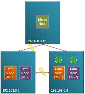
Fig 3. Half of data nodes lost

Fig 3. Half of data nodes lost

In Fig 3. host 192.168.0.3 and its 2 data nodes remains up and running but becomes isolated from the management node and the other data nodes. 2 communities of connected data nodes are formed. As each of these communities are viable but recognize that there could be another viable surviving communitycontain a data node from each node group, they must defer to the management node. As192.168.0.3 has lost it’s connection to the management node, the community of data nodes hosted there shut themselves down. The community hosted on 192.168.0.4 can contact the management node which as it’s the only community it can see, allows its data nodes to stay up and so service is maintained.

.

.

.

Example 3: Half of data nodes isolated and management node lost
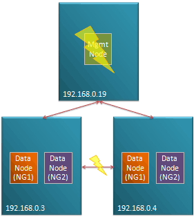
Fig 4. Data nodes isolated following loss of management node

Fig 4. Data nodes isolated following loss of management node

The scenario shown in Fig 4. builds upon Example 2 but in the case, the management node is lost before one of the data node hosts loses its connection to the other.

In this case, both communities defer to the management node but as that has been lost they both shut themselves down and service is lost.

Refer to Example 1 to see what steps could be taken to increase the tolerance to multiple failures.

.

.

.

.

.

Example 4: Management node co-located with data nodes
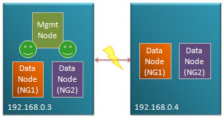
Fig 4. Management node co-located with data nodes

Fig 5. Management node co-located with data nodes

Fig. 4 shows a common, apparent short-cut that people may take, with just 2 hosts available hosting the management node of the same machine as some of the data nodes. In this example, the connection between the 2 hosts is lost. As each community is viable they each attempt to contact the arbitrator – the data nodes on 192.168.0.3 are allowed to stay up while those on 192.168.0.4 shut down as they can’t contact the management node.

However this configuration is inherently unsafe, if 192.168.0.3 failed then there would be a complete loss of service as the data nodes on 192.168.0.4 would form a viable community but be unable to confirm that they represent the only viable community.

It would be tempting to make this more robust by running a second management node on 192.168.0.4 – in that case, when each host becomes isolated from the other, the data nodes local to the management node that’s the current arbitrator will stay up however if the entire host on which the active arbitrator failed then you would again lose service. The management node must be run on a 3rd host for a fault-tolerant solution.

Example 5: Odd number of data node hosts
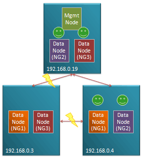
Fig 6. Isolation of data node host - majority survive

Fig 6. Isolation of data node host - majority survive

Fig 6. shows a configuration running the management node on the same host as some of the data nodes does provide a robust solution.

In this example 192.168.0.3 becomes isolated its data nodes form a community of 2 which doesn’t include a data node from NG2 and so they shut themselves down. 192.168.0.4 and 192.168.0.19 are still connected and so they form a commiunity of 4 data nodes; they recognize that the community holds all data nodes from NG2 and so there can be no other viable community and so they are kept up without having to defer to the arbitrator.

Note that as there was no need to consult the management node, service would be maintained even if it was the machine hosting the management node that became isolated.

.

.

Example 6: Loss of all data nodes in a node group
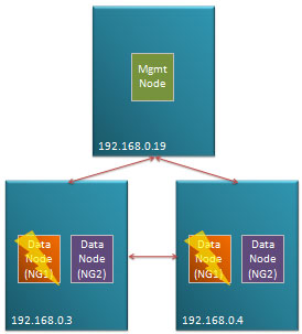
Fig 7. All data nodes in a node-group lost

Fig 7. All data nodes in a node-group lost

Fig 7. illustrates the case where there are multiple data node failures such that all of the data nodes making up a node group are lost. In this scenario, the cluster has to shut down as that node group is no longer viable and the cluster would no longer be able to provide access to all data.

.

.

.

.

.

.

Example 7: Loss of multiple data nodes from different node groups
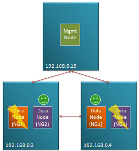
Fig 8. Data nodes from different node-groups lost

Fig 8. Data nodes from different node-groups lost

Fig 8. is similar to Example 6 but in this case, there is still a surviving data node from each node group. The surviving data node from NG1 forms a community with the one from NG2. As there could be another viable community (containing a data node from NG1 and NG2), they defer to the management node and as they form the only viable community they’re allowed to stay up.

.

.

.

.

.

.

Example 8: Classic, fully robust configuration
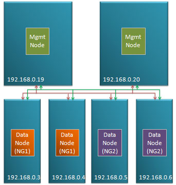
Fig 8. Robust configuration

Fig 9. Robust configuration

Fig 9. shows the classic, robust configuration. 2 independent machines both host management nodes. These are in turn connected by 2 independent networks to each of the data nodes (which are in turn all connected to each other via duplicated network connections).



Free webinar: FreeRADIUS & MySQL Cluster: Scalable and Highly Available AAA Services – EMEA

FreeRADIUS And MySQL ClusterAs network use grows and services become more dynamic, so existing Authentication, Authorization and Accounting (AAA) environments can struggle to keep pace with demand.

Tune into this webinar where you can hear from the Alan Dekok, one of the founders of the FreeRADIUS project and CEO of Network RADIUS, discuss the concepts and implementation of RADIUS services using the FreeRADIUS server and the MySQL Cluster database to deliver highly available and scalable AAA services.

As always, this webinar is free and you can register here. I will be manning the Q&A during the webinar.

In this session, you will learn about:

  • potential AAA limitations as network environments grow
  • advantages of deploying FreeRADIUS with MySQL Cluster
  • Performance, sizing and deployment of an AAA environment using FreeRADIUS with MySQL Cluster
  • customer case studies
  • how to get started

WHO:

Alan Dekok, Founder of the FreeRADIUS project and CEO of Network RADIUS
Matthew Keep, MySQL Cluster Product Management

WHAT:

FreeRADIUS & MySQL Cluster: Scalable and Highly Available AAA Services web presentation.

WHEN:

Tuesday, October 20, 2009: 10:00 Central European time

Tue, Oct 20: 09:00 Western European time

Tue, Oct 20: 11:00 Eastern European time

The presentation will be approximately 45 minutes long followed by Q&A.

WHERE:

Simply access the web seminar from the comfort of your own office.

WHY:

To learn more about how you can use FreeRADIUS and MySQL Cluster 7.0